
A technical perspective on 2T and 4T perovskite tandem PV architectures
.png)
Increasing the power output of solar panels has been the driver for most technical innovation in the PV industry. The move from Al-BSF (~20% cell efficiency) to PERC (22–24%), then TOPCon (24–26%), HJT (24–26%), and back contact (BC) (25–27%) cell structures in mass production has been driven by increases in cell efficiency. Just a 2% absolute gain in efficiency motivates the significant capital investments for PV manufacturers to transition to next-generation cell technology. Similarly, module makers have been increasing the size of modules to generate more power (and revenue) per module and make system installation more cost-effective.
These increases in cell efficiency and module power have driven down PV system costs, but there is very little room to improve from here. Silicon cell efficiency is reaching its theoretical limit, and modules cannot get much larger without introducing new field failure modes and becoming impractical for installers to handle.
This is where perovskite-silicon tandem technology comes in. Tandem cell efficiencies approaching 35% and module efficiencies up to 30% have already been demonstrated. Tandems offer the biggest step in efficiency and module power in the history of PV technology.
There are two main architectures used for perovskite-silicon tandem PV cells and modules, defined by the number of electrical terminals used—two-terminal (2T) and four-terminal (4T). The differences are illustrated below at both the cell and module level.
.png)
At Swift Solar, we are often asked why we focus on the 2T perovskite-silicon tandem structure and what the differences are.
We start by thinking about what makes for the best final product. In most use cases, the “best” PV module delivers the most power in a given area, with the longest operating lifetime, the most reliably, for the lowest installed cost. With this in mind, we focus here on three key metrics that a new PV technology must excel in:
The 2T tandem architecture beats the 4T architecture in all 3 of these critical metrics.
Depending on the use case, the weighting of these factors can change a little bit, and the reason for a customer to adopt a new product may vary. For traditional use cases such as utility, commercial, and residential PV installations, the main reasons customers accept the risks associated with new tandem technology is the efficiency gain and associated system-level cost savings. The main risk that must be mitigated for any new technology is reliability (field lifetime).
There is further room for performance gains by transitioning from a double junction perovskite-silicon tandem to a triple junction perovskite-perovskite-silicon tandem architecture—the practical limit increases from 39% to 44% (1). The 2T approach lends itself most naturally to triple junctions, and its efficiency benefits are even stronger for triple junctions.
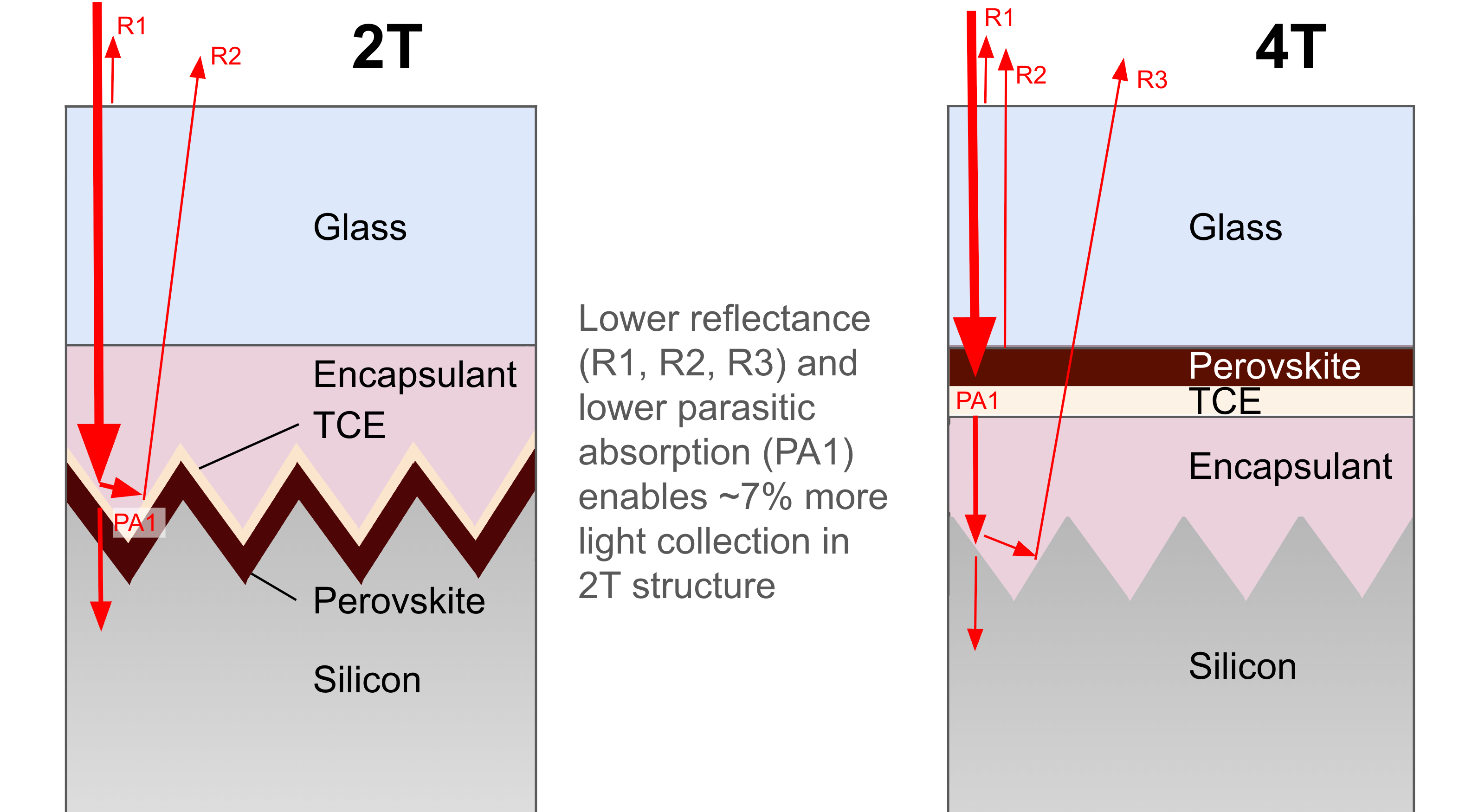
Losses from light reflection and parasitic absorption in the electrodes are minimized in 2T tandems, translating to a 7% relative (2% absolute) increase in module efficiency and annual energy production compared to 4T tandems.
The 2T structure has a higher efficiency limit than the 4T structure simply because there are fewer optical losses—more light is usefully absorbed by the solar cell rather than reflected or absorbed by inactive layers. In practice, this is observed in the 2T and 4T efficiency records: 34.85% (1) certified efficiency for 2T vs. non-certified reports of 30–31% for 4T.
Light trapping
Because any perovskite solar cell consists of many thin layers (<1um thick), light tends to reflect out of the cell if it is made on a smooth, flat surface. If the perovskite top cell can be made on a front-side textured silicon cell—a significant technical challenge—the resulting tandem cell benefits from the same light trapping mechanism as commercial Si cells, mitigating reflection losses. Making the perovskite top cell compatible with textured surfaces enables a 3–5% relative efficiency increase at the module level, compared to a module with no cell texturing. Because 4T tandems use smooth glass coated with thin transparent electrodes as the surface for depositing the perovskite on, the 4T structure loses 3–5% relative efficiency to light reflection and absorption.
Realizing the full efficiency potential of perovskite-silicon tandem technology requires coating on textured silicon cells, but standard solution-based perovskite deposition methods used by most companies make this very difficult. This is one reason many US companies have chosen the 4T structure. However, in an industry where every 1% in efficiency is important, solving this problem is valuable. Swift Solar has prioritized and mitigated this challenge, unlocking the path to the highest efficiencies.
Parasitic absorption
Collecting current from a perovskite solar cell requires the entire area to be covered with a conductor. In a tandem structure, that conductor has to be transparent so infrared light can pass through the perovskite cell and into the silicon cell. Thus, tandem solar cells must use transparent conducting electrodes (TCEs), which usually employ a conducting metal oxide which may contain tin, zinc, aluminum, and most often indium. These materials are used widely in the display industry and in HJT and CdTe PV cells, but are still limited in their tradeoff between conductivity and transparency. To collect the current as effectively as possible requires a thick layer, but the thicker the layer is, the more light it parasitically absorbs and the less light is transmitted to the silicon cell.
4T architectures require more and thicker TCE layers than 2T designs. The 2T structure can use the conventional front metal grid used in commercial Si cells* and only pulls current from the top and bottom of the entire tandem cell. In contrast, the 4T structure generally requires current to be extracted independently from both sides of both the top and bottom cells, which requires over 5x more TCE material. This results in more than double the optical loss, corresponding to an additional ~3% relative performance drop compared to 2T structures.
Leveraging advances in silicon cell technology
With the ability to deposit perovskites on rough and textured surfaces, 2T tandems can be built on both HJT and TOPCon silicon solar cells with minimal modification, and 4T tandems are Si cell agnostic due to deposition being decoupled. These are the two high-efficiency Si cell structures that are expected to dominate global production for the next decade, so both 2T and 4T tandems are well-aligned with the silicon technology roadmap.
Back-contact (BC) silicon is an alternative technology with the highest efficiency in the Si roadmap. Given the advances in and increasing commercial production of BC cells, one could argue that 4T tandems have a path to leveraging the highest-efficiency silicon cells. By placing all contacts underneath the solar cell, the BC design removes shading from the front metal grid and allows the use of insulating and transparent passivation on the front. Because optical losses from front side metalization and interconnects are so small (~0.3% absolute) with today’s multi-busbar technology, the primary benefit of the BC structure is in avoiding parasitic absorption of visible wavelengths in the amorphous silicon passivating layers used in HJT cells. In a tandem structure, however, this parasitic absorption has no impact, because those wavelengths are already absorbed by the perovskite top cell. Therefore the benefits of BC over HJT and TOPCon silicon bottom cells in a 4T structure are minimal and do not represent a significant advantage over 2T.
Altogether, the practical efficiency potential for the 2T tandem module is ~7% relative (2% absolute) higher than the 4T tandem module. Historically, this has been enough of an efficiency gap to cause industry-wide shifts and investment in new cell technology.
Energy yield
For higher efficiency to translate to higher value to the customer, the module must output a proportionally higher amount of energy in the field.
In a 2T tandem, the output current is limited by the current-limiting subcell, so it is beneficial to have both subcells current-matched. In a 4T, there is no such requirement, but the perovskite and silicon submodules must either be MPP-tracked separately (expensive) or voltage-matched to have only two output leads. Because the current-matching requirement can be relaxed in the 4T structure, and the solar spectrum varies throughout the year and throughout the day, 4T proponents argue that 4T tandems will provide a higher energy yield, offsetting their lower efficiency under standard test conditions (STC).
However, data shows that this is not as big a deal as many assume. The impact of current mismatch in a 2T tandem through the year is somewhat minimized because 1) while lower current in one subcell negatively impacts the short-circuit current (Jsc), it improves the fill factor, reducing the total impact, and 2) most of the energy is generated during long sunny days for any PV technology, so the energy yield is always weighted heavily toward those days. On such days, the solar spectrum is most similar to STC, where the 2T tandem has no disadvantage relative to the 4T tandem.
Taking these effects into account, modeling by multiple research groups (1, 2, 3, 4) has demonstrated that if the same STC efficiency is assumed, a 4T tandem will deliver at most 1.5-2% (relative) more energy than a 2T tandem in a year in various locations and with single-axis tracking. Some 4T module makers suggest using additional inverters to combine the outputs of the perovskite and silicon submodules in a string. This would add an additional efficiency loss ranging from 1% to 5% relative, depending on the specifics of the inverter (in the chart below, we assume a conservative 1% loss).
This all translates to a ~7% higher system-level annual energy output (kWh/yr) for a 2T tandem relative to 4T.
%20copy%202.png)
Lower TCE requirements give 2T tandems a potential cost advantage of ~5 ct/W (10–20%)
One reason that modules that produce more energy for a given area are attractive is that they allow savings at the PV system level—especially on installation hardware and labor, which are significant portions of the installed cost for all types of PV systems. Estimates (1) suggest that each 1% increase in absolute module efficiency can save ~2% of total US utility-scale system cost, with additional benefits for area-constrained systems. A 30% efficient module would produce ~20% system cost savings. That said, if the tandem module cost ($/W) is significantly higher than traditional Si modules, this benefit is negated. For US utility-scale systems, each 1% efficiency gain should increase the module price by no more than ~2 ct/W.
Our cost modeling suggests that the perovskite top cell does not dominate the cost structure of 2T tandems for either solution or dry coating. At scale, the silicon cell, the perovskite cell, and module components (glass, encapsulant, junction box) all contribute meaningfully to the cost of a 2T tandem module. The modifications to the silicon cell in a 2T tandem have only a minor impact on the total cost at scale, especially for HJT technology, where one process step is simply made thinner (and hence less costly) than the standard process. For TOPCon cells, a thin recombination layer is required between the subcells, usually consisting of the same TCE material.
This compares favorably to the 4T structure, which requires much higher (~5x) total TCE thicknesses (see above)—implying higher materials, labor, and capex costs. We estimate that in a 4T tandem, indium-containing TCE layers in the perovskite cell will be ~4x more expensive than for the 2T tandem, potentially translating to ~5 ct/W added cost—compare this to typical module prices of ~25 ct/W in the US today (or ~45 ct/W for fully US-made modules).
Continuous barrier layers and conductive front electrodes enhance 2T tandem lifetime, and the 2T structure improves reliability by mitigating reverse bias breakdown during shading events and helping mitigate UV-induced degradation.
%20copy.png)
Since its inception Swift Solar has focused intensely on understanding and mitigating stability concerns in perovskite solar cells. Based on learnings from our work and the broader community, we see two major stability benefits of a 2T singulated tandem cell structure over a 4T tandem structure with a monolithically interconnected perovskite submodule—reduced degradation risks and greater reverse-bias resilience.
Reduced degradation risks
The combination of heat (high temperature) and light is a uniquely stressful situation for perovskite solar cells. During combined heat and light exposure, the ions in a perovskite lattice can become mobile, which leads to one of the major causes of perovskite degradation. Small, mobile halide ions—as well as some organic A-site components—can be volatilized and lost from the perovskite layer. This breaks down the structure of the perovskite lattice, causing degradation. To stop this mechanism, an ion-blocking layer can be deposited above the perovskite layer, preventing or slowing ionic egress. This has been shown to be an effective strategy to minimize this degradation pathway.
In a 2T module, tandem cells are processed as individual units, so an ion-blocking layer can completely cover the entire cell without issues. In a 4T module, however, perovskite cells are formed by laser-scribing a larger module area with the perovskite layer already deposited. This scribing process is a serious concern for degradation—each scribe line cuts through an ionic barrier deposited above the perovskite layer, creating large egress pathways for volatile ions to leave the cell, causing degradation. Depositing an ion-blocking layer after scribing is extremely difficult, as it requires uniform coverage of the laser-damage-induced rough interfaces at the scribe line.
Perhaps more critically, the laser scribing itself can cause damage to the perovskite layer adjacent to the scribe lines due to the severe local heating necessary to remove the perovskite material. Once degradation is initiated, it can accelerate rapidly with the initial degraded area as a nucleation point. Laser-induced damage can thus accelerate the start of other degradation processes in a 4T tandem.
Greater reverse-bias resilience
Another major reliability benefit of the 2T structure is resilience to partial shading. When a solar panel is partially shaded—often by trees, dirt, bird droppings, chimneys, antennae, etc—the shaded area produces less current. Since other cells in the module continue to produce full current, a shaded cell may be pushed into reverse-bias breakdown to allow current from the illuminated cells to pass through it.
Perovskite cells have been shown to undergo irreversible damage very quickly when experiencing reverse-bias conditions, so this is a critical module-level stability concern. Other solar technologies also have problems in reverse bias—silicon modules incorporate a few bypass diodes per module to allow current to flow in an alternative pathway when partial shading occurs, preventing damage. Only a few diodes (~1 per 20 cells) are needed because silicon can sustain a high voltage in reverse bias before breaking down. Perovskites break down at a lower voltage, meaning a similar protection strategy would require one diode per 1–2 cells.
This is where the benefit of a 2T structure comes in—by building the perovskite cell directly on the silicon cell, the silicon subcell protects the perovskite cell in reverse bias. A 2T tandem can sustain a high reverse bias voltage before breaking down, similar to silicon. This means that a 2T tandem module can use a roughly similar number of bypass diodes (at most 2–3x) as a silicon module to protect from reverse bias damage in partial shading.
In a 4T module, this benefit does not exist—the perovskite subcells will break down at a low reverse voltage. To avoid damage in partial shading, such a module would need to add a bypass diode every 1–2 cells for the hundreds of perovskite cells in a 4T module. This is impractical and expensive in production. One would have to add bypass diodes at the edges of the module, but current cannot travel well enough along the full cell/module width to make that work anyway.
We believe reverse bias susceptibility will be a major problem for 4T tandems. Partial shading is a particular issue for rooftop and C&I systems with many sources of artificial shading, but even in utility-scale deployments it can occur due to cleaning apparatuses, dirt, bird droppings, or even cloud cover, depending how sensitive the module is. This issue may completely rule out some markets for four-terminal tandems.
Other 2T reliability benefits
Another stability consideration where 2T tandems come out on top involves local degradation of the module—for example, in the case of edge seal failure (and subsequent moisture ingress) or local delamination.
Because monolithically interconnected 4T designs have many cells in series with effectively no lateral conduction across cells, if 10% of one cell degrades (~0.1% of total module area), 10% of the entire submodule is effectively degraded. In a 2T design, individual cells are much larger, so the same 0.1% of module area is less than 10% of one cell, so less relative loss is incurred for the damaged cell. Furthermore, 2T modules generally consist of multiple strings, so at most a fraction of the module is impacted at all—the other strings are unaffected.
Finally, UV exposure is known to cause performance loss in many types of solar cells, including perovskites. One UV-related degradation mode is the degradation of organic semiconductors commonly used in the hole transport layer. This problem is particularly important for the 4T structure, where the hole transport layer is directly exposed to UV light—in a 2T structure, other cell layers protect the hole transport layer from UV exposure. Perhaps more importantly, a 2T structure can easily incorporate a UV blocker in the encapsulant between the cell and front glass—a 4T structure cannot use this approach since the perovskite cell is built directly on the front glass.
2T tandems enable higher manufacturing yields and unique access to high-value markets.
Because a 2T module is made up of many (e.g., 72) individual cells, it is possible to bin cells by efficiency, and even remove cells that contain problematic defects. For example, if 1 in 72 cells has a defect and is discarded, the production yield can still be >98% with high-performing modules. For 4T modules, on the other hand, defective areas cannot be removed—the entire module is impacted, especially because the lateral conduction of the TCE is so low. In this case, the same 1-in-72 density of defects per area would limit the performance of every module made.
Making individual 2T tandem cells rather than coating directly on the module glass also opens up alternative applications. For example, satellites deployed in low earth orbit (LEO) are powered by PV arrays that use different encapsulation materials from a conventional PV module—with 2T tandems, cells from the production line can simply be diverted to a different space-compatible backend process. For early low-volume production of a new technology, such high-value markets requiring more flexibility can provide a valuable source of early revenue. 4T production lines are practically limited to one module format, making it more difficult to address markets with different form factor requirements.
2T tandems enable future development of triple-junction modules with PCEs over 40%.
The drive toward more powerful modules will only continue.
At Swift Solar, we believe that the next step for PV technology development is a triple-junction perovskite-perovskite-silicon tandem cell enabling over 44% cell efficiency (1). The 2T approach is best suited to enable this future. The reflection and parasitic absorption losses described above limit the attainable efficiency of a triple-junction cell design even more than a double junction. Building tandems directly on top of textured Si cells mitigates optical losses, enabling the highest efficiency. The benefits of the 4T (or 6T) structure for minimizing current-matching constraints will be eliminated in a triple-junction design—there is no practical design that would enable independent operation or voltage-matching of three submodules.
While the 4T structure is a convenient way to make double-junction tandem modules with fewer technical challenges in coating the perovskite layer, it is less compatible with the long-term future of PV—both in terms of efficiency potential and compatibility with triple-junction architectures.
Swift Solar’s 2T perovskite tandem architecture offers a clear path to high module efficiencies in the short term through double-junction designs, and sets us up to continue driving PV module efficiency upward for decades to come.

